.png)

Leopard undergoes Environmental Testing before space voyage
The last few weeks were quite intense for our Intuition-1 mission as its core component went through a thorough environmental testing campaign. That is a good reason to briefly describe the entire process and stress its importance to the eventual success of the mission.
If you’re following the KP Labs news and projects, you probably know the goals of the Intuition-1. As a brief reminder, the Intuition-1 will demonstrate the ability to carry out an autonomous analysis of the satellite’s hyperspectral data. To make that happen, the Intuition-1 is equipped with two key hardware components: an extremely powerful Data Processing Unit (DPU) called Leopard, which is responsible for running neural networks analysing the hyperspectral images, and an Optical Instrument called Eagle that supplies Leopard with the hyperspectral images.
The importance of Environmental Testing
The key difference between Space Hardware and any other device designed to be used on Earth is the ability to diagnose the problem once the malfunction occurs. If your car, laptop, or smartphone starts to behave unexpectedly, all you have to do is take it to a workshop or hardware specialists for diagnosis. You can touch it, watch it and perform all the measurements you need with dedicated equipment – no matter if it’s a complex car diagnostic computer or a simple multimeter. The malfunction of a hardware orbiting the Earth is a different story entirely. There’s no way to watch the device, touch it or connect any diagnostics device to it. Sometimes you can’t even restart it to see if this most-obvious-solution-ever will solve the problem. This complexity leads you to one conclusion: if you send something to Space, you have to be sure it will work flawlessly there – at least as much as you can, as you can never have a 100% certainty. You always operate on probability as the space environment can only be simulated with some limited accuracy.
In order to make sure your device will operate as expected once on orbit you basically have to do two things: first of all implement as many watchdogs, sensors and software protections as you can, so once there is a problem you get enough data sent to Earth to understand the issue and come up with a solution to fix it. The other thing you have to do is to perform a complex Environmental Testing Campaign, the purpose of which is to simulate the Space environment and observe the condition of the device. This post will describe how the testing process looked like for evaluating the Intuition-1 hardware.
An Environmental Testing campaign is designed to provide you with the answers to those critical questions:
- Will your device survive the rocket launch and its flight to the desired orbit?
- Will your device work properly in an extremely wide temperature range? And – what exactly is the safe temperature range for the device?
- Is your Thermal Control System capable of maintaining the right temperature for your device once you need it to run?
The outcome of the Environmental Tests will not only tell you if the device is going to work at all, but also provide you with critical data describing the safe environmental parameters for the device (e.g., the safe temperature levels) and based on this data, you may still be able to modify the mission plan to make sure the safety levels are not exceeded once the mission starts. To provide you with some context in terms of the Intuition-1 mission – the radiator responsible for dissipating the heat from the Optical Instrument is relatively small due to the volume limitations. Once turned on, the sensor part of the Optical Instrument generates heat that is impossible to be fully dissipated by the radiator. Professional thermal modelling combined with the results obtained during the Thermal Vacuum Chamber tests provide priceless information for both the Chief System Engineer and the Operators – it tells them how long a single imaging session can be running before the temperature of the instrument hits the upper limit of the safety range. The time of the imaging session of course impacts the power budget as well, therefore changing the duration of the processing task for the Leopard DPU…
Surviving the Rocket Ride
The start of a Space Mission is not a gentle and easy process. At the very beginning, your hardware is taken for a rocket launch, which means it has to survive the acceleration up to 19Gs. This is enough to destroy the precise device you built: if your PCBs were poorly mounted or soldered some components may detach from the PCBs. Contact areas between the electronic components generating the most heat (processors, FPGAs, RAM, SSDs) and elements of Thermal Control Systems may also be loosened leading to the decreased performance of the TCS.
For the Intuition-1 mission, the most vulnerable component in terms of exposure to vibrations is the Optical Instrument.
Have you ever taken a photograph? Of course, you probably take a few pictures every day, no matter if you rely on your smartphone or a professional camera. Focusing is quite a complex matter, isn’t it? Good thing is, our handheld cameras have knobs and buttons we can use to change the alignment of the optical elements within the lens set to make sure the subject of the photograph is perfectly sharp. In case of the Intuition-1 device, our optical instrument has a fixed focus, which means, once assembled and fine-tuned it cannot be re-focused again while on orbit. It is not always the case – it is possible to equip your optical instrument with servomotors or other mechanisms giving you on-orbit focus adjustment capabilities, however, implementation of such technology increases the complexity of the device and require a significantly bigger budget. Those two arguments were more than enough to select the fixed-focus way for the Intuition-1 Optical Instrument.
When designing an optical track there’s one universal truth: the smaller the device and the better the parameters you desire, precision becomes the biggest issue. You learn that truth twice: the first time when it turns out that designing the optical track is one thing and the ability actually to manufacture it is something else entirely. The second time you learn this truth is when you have all the required pieces in your lab, both mechanical and optical parts, and you attempt to assemble and align the optical track. You realise that achieving the alignment precision of a few micrometers is extremely hard – especially since each element of the optical track can be aligned in the X, Y, and Z-axis along with the tip-tilt adjustment. Once the alignment is finished and you are happy with the results – you have to make sure that the vibrations the device is about to face during the rocket launch will not misalign it. During one of our vibration tests, one of the optical elements moved in one axis by 50 micrometres (0.05mm) and that made the perfectly sharp optical image unsharp.
Testing the ability to survive the Rocket Launch begins with a meticulous test procedure design. Different launch providers and rockets result in different vibration profiles you have to comply with (Sine vibration, random vibrations, shocks). If you have your launcher selected when undertaking the environmental testing campaign, you simply test your device by the profile of that launcher. However, it is a common case that the launcher is not yet selected – this is the scenario of our Intuition-1 mission. According to our Launch Agreement, which is signed by Clyde Space the key requirement for the Intuition-1 launch is the desired orbit and the time window as the mission schedule is quite demanding. Based on that the actual launch operator and the rocket itself will be chosen at the latest possible moment, which means it is not known during the vibration tests. In that case, you have to test your payload against the worst-case scenario from all the possible rockets that may take your device into Space.
Once the test is designed and you know the vibration profiles you want to test against, you have to prepare your payload for that test. First of all, you have to find a facility capable of executing the test. There are companies that own the vibration slip tables, the device used to perform the vibration test, however, it is not always the case. KP Labs does not have its own device, therefore a supplier had to be found. The process is not easy – first of all not slip tables are able to execute the desired vibration profile. Once the supplier is selected – and the schedule, budget and required vibration profiles are agreed you have to prepare the MGSE – Mechanical Ground Support Equipment, which depends on the vibration bed your supplier owns. Long story short – this is the mechanical construction that tights your component under test (Leopard or Eagle) to the slip table.
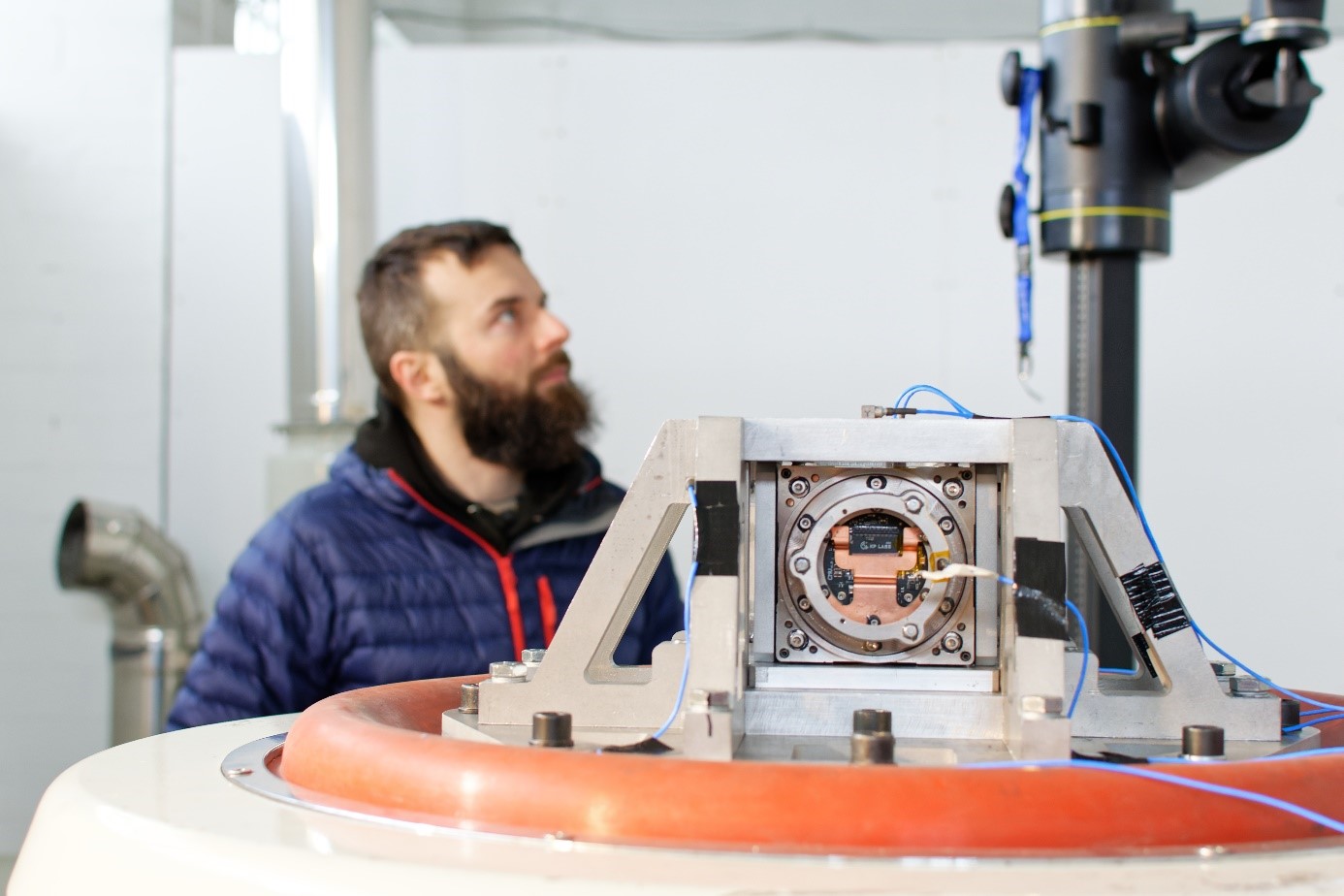
Figure 1: Eagle instrument on the vibration bed.
Finally, when the vibration test is executed, you shake the device according to different vibration profiles the device can meet. There are a few scenarios which you can face:
- The fastest one – something goes wrong, and you have to abort the test. There can be different presumptions for that: you can simply see and/or hear that something has broken while being shaken. Alternatively, you may see on the real-time data from accelerometers attached to your device that readings of those sensors changes while they should not, even if there is no visible damage to the device. Once aborted you have to examine what went wrong and that usually means taking the device back to your headquarters for a detailed analysis. We faced that scenario during the first test of the Eagle.
- The more time-consuming one – nothing brakes during the vibration test. Although it may sound like a total success, in fact, it is nothing more than an open door for more analysis.
If you claim the vibration test to be successful, the first thing you do is executing the functional tests to make sure the device still works properly. In case of the Leopard, you run the defined set of software tests. If successful – great, you can move forward. If not – well, good luck with designing another iteration of your hardware.
In case of our Eagle the matter is more complex. Of course, you still execute the fast functional test to check if the sensor still works and is capable of undertaking its imaging tasks. However, the key question after shaking is checking if the image obtained by the Instrument is exactly as sharp as it was before the test. It is quite a complex matter and requires comparing the before/after “focus map” of the sensor.
Once you are sure that you can put a tick next to the “Vibration test” you can go to the next stop of your Environmental Testing Campaign.
Surviving the Vacuum
If you are reading this post on your laptop or a classic PC, you probably noticed the fans being turned on a few times already as your processor was running too hot. As simple as that – if your piece of hardware starts to overheat just turn on the fan, make some airflow to cool it down and voila – your hardware is back to its nominal temperature! If only things were so easy in Space…
Once your satellite is put on orbit the only way to get rid of the heat is the radiation. There is no air, so no fans can be used. You can only use radiators facing the deep space to cool your device down. During the design phase you use complex computer modelling to design the TCS, but it is the test in Thermal Vacuum Chamber that tells you if your TCS is working as expected. In other words – this particular test gives you an answer if the radiators, TIMs and other components of the TCS work as designed.
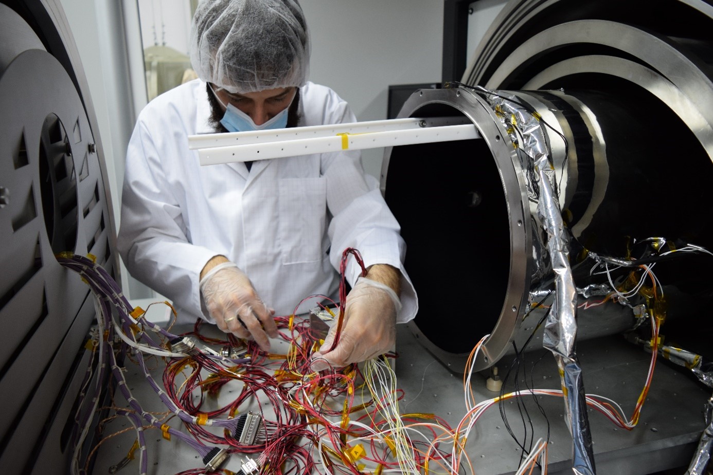
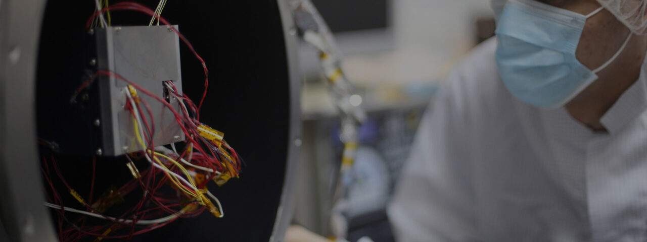
Figure 2: Preparing Leopard for a TVAC test.
The Thermal Vacuum Chamber does two things, which you can guess by its name: generates vacuum and allows you to easily change the temperature inside it. Usually, the scenario follows a similar pattern: once the chamber is vacuumed, you set the interior temperature to the upper or lower limit of your hardware safety range, run the device and check if it works – during the test. Of course, the operation is technically complex – the device put in the chamber must be able to be turned on and controlled from the outside to monitor its functions. It is extremely helpful to have internal temperature sensors, which you can monitor (e.g. sensors already built-in SoCs you use) along with the external sensors you attach to the critical components you need to monitor. Leopard had many temperature sensors, both internal and external that monitored the temperature of SSD, RAM, FPGA units, power converters and some selected locations on PCB in a real-time mode. During all of the tests, our engineers have a real-time view on the data.
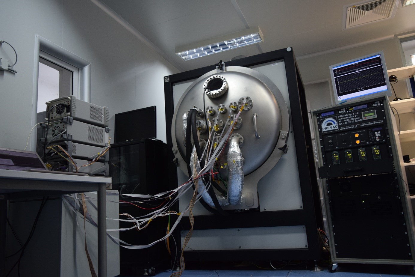
Figure 3: Leopard inside the TVAC!
Defining nominal temperature
The last element of the environmental testing campaign is the climatic chamber test. This one has to answer one question: what are the safe temperature levels for your electronics in both hot and cold cases?
There’s no surprise that electronic devices do not necessarily like when it is too cold or too hot. While too hot may be an obvious thing for you as you probably faced the issue of an overheating computer, the extreme cold is dangerous as well. To find out what temperatures are safe you put your device in a climatic chamber – the laboratory device designed to easily change the inside temperature from low to high (and vice versa).
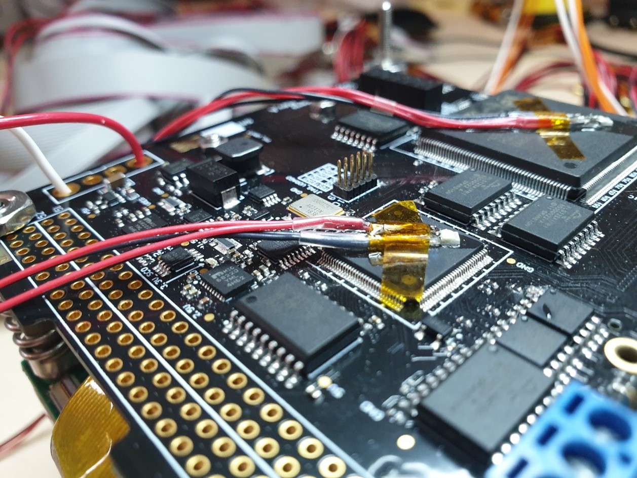
Figure 4: Attachment of the thermal sensors to key components.
In case of our Intuition-1 tests, we set the minimal temperature to -40°C and maximal to +80°C. During the temperature shift attached temperature sensors provided us real-time feedback regarding the temperature on core components like FPGAs, RAMs, SSDs, power converters etc.
Besides monitoring the temperature levels on core elements and changing the temperature inside the test chamber the test team was changing the state of the Leopard unit itself: from the disabled state to low-power house-keeping, to executing classic computing algorithms to full-power neural network processing of benchmark hyperspectral data.
Final words
Although all of the environmental testing campaign elements are common, the order of those tests may be different. It usually depends on the team to agree on which approach would be best. From the practical point of view, the vibration test is considered to be the most destructive test, while the climatic chamber is the least intrusive one.
There are also considerations regarding the qualification strategy: you can either choose QM/FM approach when you introduce heavy tests to your Qualification Model – but that piece will stay on Earth, while the Flight Model will be later on put under much easier tests and eventually go into space. Alternatively, you may choose a ProtoFlight approach, when the test campaign is introduced to the piece of hardware that will be put on orbit, in which case, the test levels are lowered. The choice is not easy – you either accept a bigger cost for the campaign (more hardware needed) and get more detailed results or – you’re saving more money but your risk of unexpected malfunction gets higher.
We hope this post helped you understand the complexity of the Environmental Testing Campaign and you appreciate all the efforts our team has undertaken to make sure the mission will be a successful one.
Author: Grzegorz Łada | Project Manager Intuition-1
More news
Stay informed with our latest blog posts.

John Doe
CEO, XYZ Corp
Jane Smith
CTO, ABC Inc
Mike Johnson
COO, DEF Corp
Sarah Williams
CFO, GHI Inc


